The vertical stabilizer was constructed in a female mold made from low density foam. The foam mold was cut with a hot wire process using aluminum templates with airfoil coordinates generated by the Delft Institute of Technology. All wing and vertical stabilizer templates were cut using an NC laser cutter. The structure of the vertical stabilizer is a balsa core sandwiched between layers of an aramid fabric. The 4mm medium density balsa core was again used as a structural member carrying a major portion of the stabilizer bending moments. All efforts were made to keep the weight of the stabilizer to a minimum while meeting CS 22 design criteria. Again many extra man-hours and costs are associated with using this building technique. Shaping the balsa core, adding stringers to the stabilizer skin for maintaining stability, and the use of aramid (Kevlar 49) fibers were all driven by the need to reduce weight. Inherently an open class sailplane tends to be tail heavy. The increased length of the tail boom to achieve good handling qualities normally results in an aft cg. Although the neutral point shifts aft with the increased tail boom length it does not overpower the aft movement of the cg and therefore the addition of nose ballast is normally required. Every effort was made to minimize this trend in Concordia. The end result was a vertical stabilizer almost 30% lighter than that of the Eta Biter (modified ASW22 sailplane). The following photos summarize this building process.
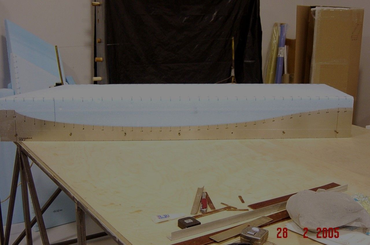
The photo above shows a section of the vertical stabilizer ready for cutting with hot wire. A thin layer of phenolic material simulates the thickness of the stabilizer skin coating and will be bonded to the foam. This results in a smooth surface and allows the templates to later be used for contouring the vertical stabilizer.
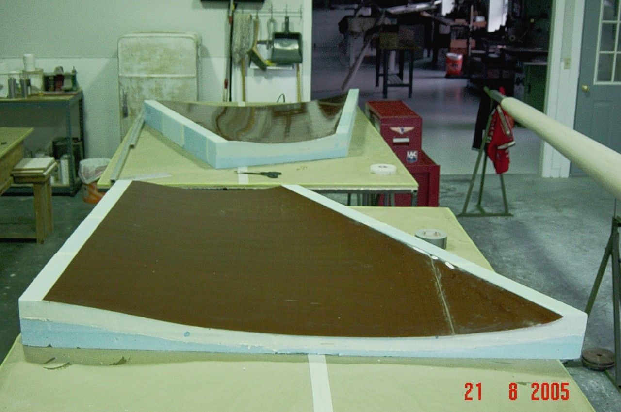
The preceding photo shows the vertical stabilizer molds cut with the phenolic material bonded in place. The molds are now ready for lamination of stabilizer and rudder skins.
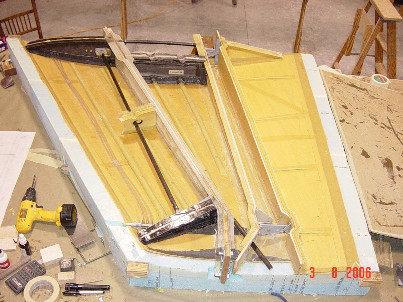
The photo above was taken after the vertical stabilizer internals had been installed and the structure was nearing the point of closure.
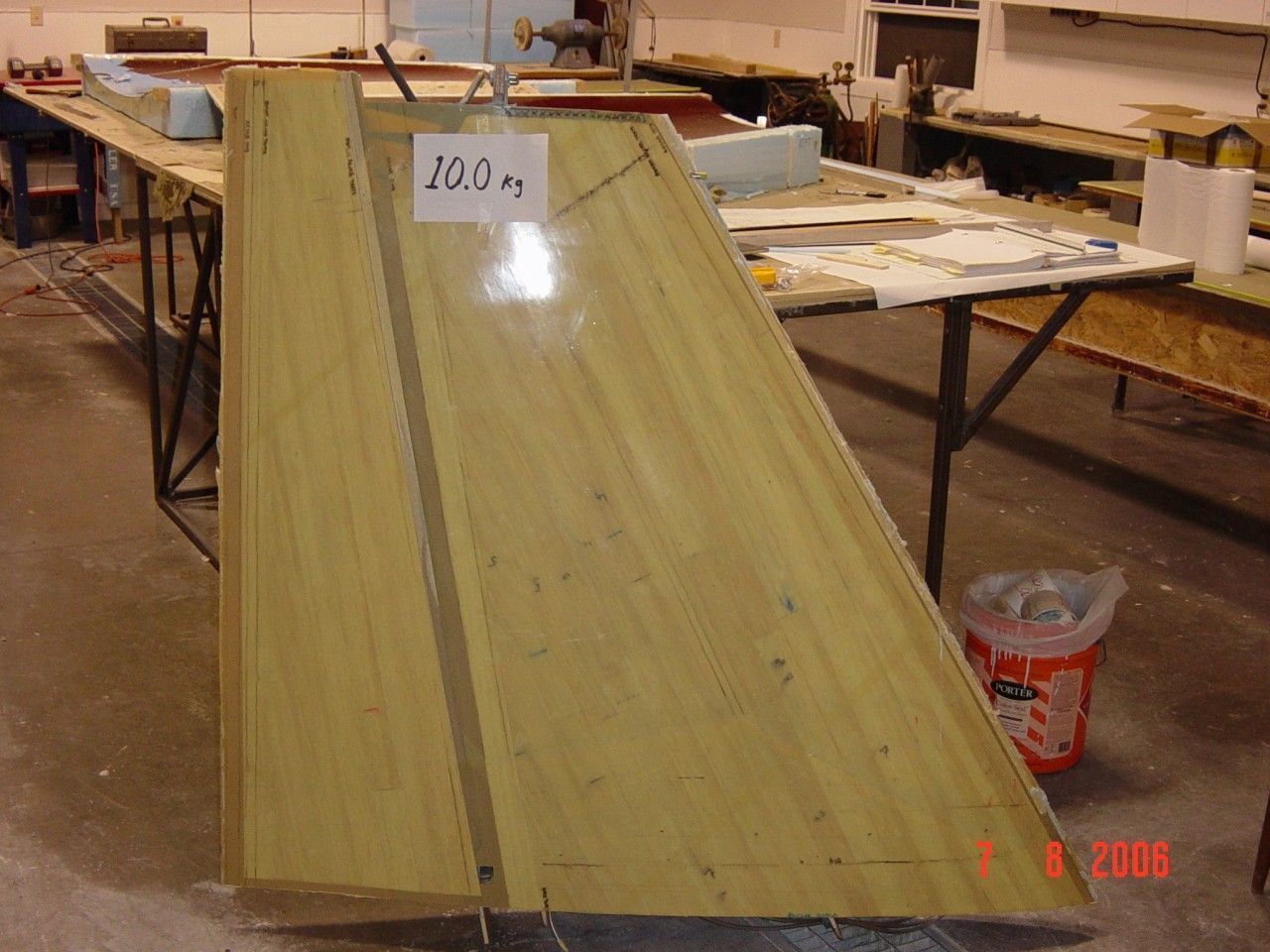
In this photo, the vertical stabilizer is closed and ready for installation on the fuselage. The design weight of 10kg was achieved, much to the satisfaction of Waibel and Butler.
Thanks for leaving that DeWalt cordless drill in the picture frame – I have an identical model and it gave me a good sense of scale ;-).
Would it be possible to see this with my own eyes while I'm down at Benton for the Sports Class Nationals? I suspect this would be a great rain-day event if you wouldn't mind a bunch of awe-struck glider pilots! ;-).
No problem, call to make sure I am home, you are welcome. dick
Second Franks request to see this ship live when in Benton for the Sports Class Nationals! Would be a great way to spend an unflyable day. Love the articles on this glider…thanks.
Great report. Thanks so much for sharing.
I hope you didnt forget the Radio Antenna 🙂
KT I believe the use of Kevlar makes it unusable as a radio antenna placement.
Actually, I think that aramids are pretty much transparent to radio waves. I have put antennas inside aramid structures before. Thanks, Bob K.
Mr. Butler,
I am an engineering student at Iowa State University and my group and I have chosen to discuss the manufacturing processes of sailplane wings. I was wondering if I could discuss with you in more detail about your products design matrix and manufacturing processes to better understand the decisions and work that goes into manufacturing a sailplane wing. Thank you for any of your time Mr. Butler. I wish you the best of luck on your project and I hope the design turns out as you would like.
– Edward
Edward,
I'm an ISU Aerospace Engineering alum. Would like to get ahold of you, could you email me at abcondon@gmail.com? Thanks!