No one could have predicted the time and complexity involved in designing, building and installing the Concordia flight control systems. As discussed in preceding chapters, very few compromises were made in the Concordia wing design from the viewpoint of aerodynamics and handling qualities. On paper it was a lot of fun designing a supership and not having to worry about production time, associated costs, and being able to market the plane at a competitive price. In reality a lot of the design choices that were made to maximize competition performance came back to haunt us in the building and installation of controls. The very limited space within the wing necessitated by the thin airfoil and narrow wing chord made the control system installation very labor intensive. Based on the marginal glide path control of the Eta Biter with landing flaps, it was imperative that we find a way to provide better glide path control for Concordia. In the Concordia design, we elected to use only one set of spoilers located at the spanwise center of pressure, but with 50 degree landing flaps for both inner and middle wing panels. The additional flap area at 50 degrees would be twice the flap area on the Eta Biter and should improve glide path control. In addition to the increased flap area, Concordia will incorporate a belly chute for very short field landings. We hoped that we could use many of the ASG29 mixing systems for providing aileron, camber changing flap, and landing flap control. Unfortunately all of the ASG29 systems had to be miniaturized to fit within the Concordia wing and many new systems were invented to meet our goals. In addition, all control systems for the inner wing had to be isolated from water ballast since it was going to be necessary to carry water both forward and aft of the wing spar to achieve the maximum takeoff weight (MTOW) of 850 kg. The following photos and accompanying explanations will give readers an idea of some of the challenges we faced.
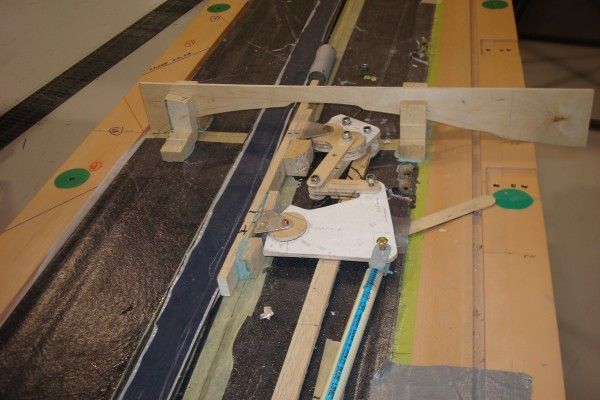
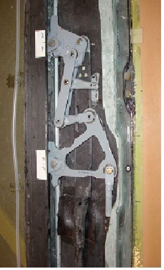
Final design of above mock up system. Between Waibel, Michael Greiner, and Butler, the control system kinematics were finally worked out so that the design control deflections could be achieved and at the same time, the controls would fit within the limited space of the Concordia wing.
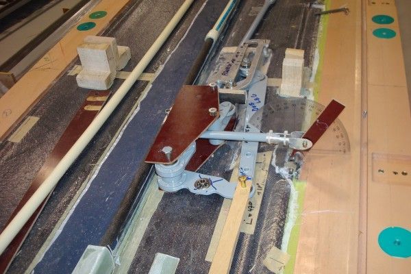
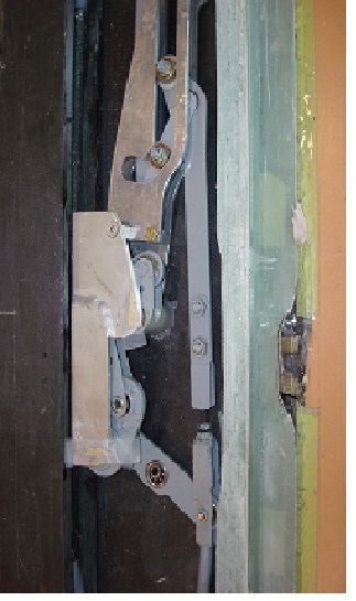
The final design of the mocked up middle wing mixer is shown in the preceding photo. This basic design from a kinematics perspective is the same as that Waibel designed years ago for the ASW20 and follow on flapped Schleicher sailplanes. The basic concept is to place all control mixing systems within the wing near the actuated control surface to minimize control deflections due to bending of the wing and associated loose motion due to long control push rods. On Concordia, this technique pushed the limit of what is possible to stuff inside the wing.
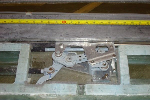
The inner wing mixer providing aileron, camber changing flap and landing flap control. Some of the complexity due to carrying water ballast aft of the wing spar can be seen in the photograph above. Both aileron and flap push rods are isolated through tubes; the mixer system itself is isolated with ribs, and the trailing spar is a hollow channel allowing water to flow past the mixer.
The next photo shows the mocked up control system for the entire wing.
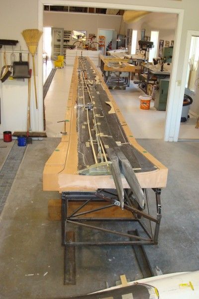
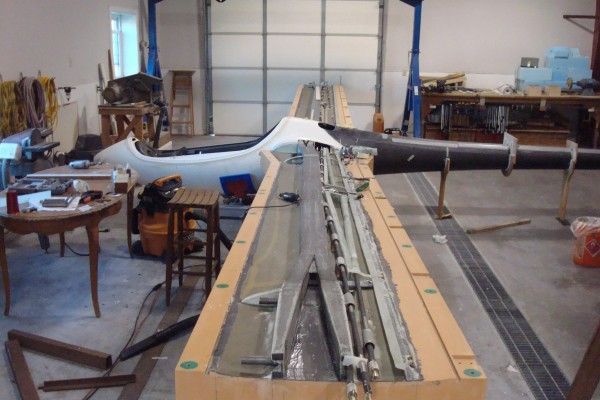
In the preceding photo, the final control system has been installed and mated to the fuselage.
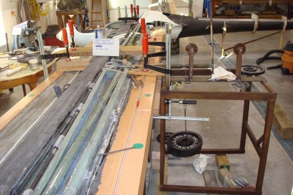
Prior to closing the wing, all control actuators were loaded to 1.25 x limit loads as specified by CS 22 to determine if all systems were stable with no flexing of push rods. The system was loaded by Christian Streifeneder and Butler and found to be good for all loadings at all aileron/flap actuator stations.
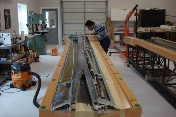
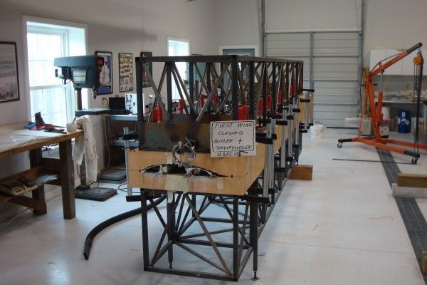
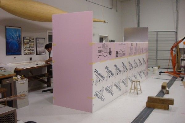
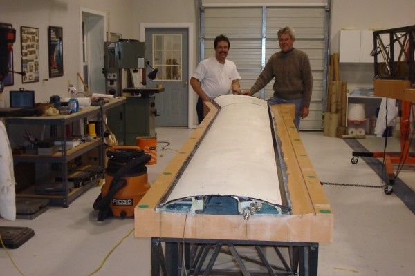
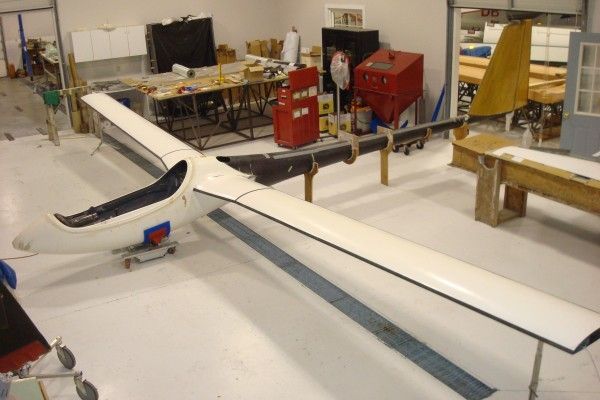
The left inner panel was closed in the spring of 2010 and is shown here mounted to the fuselage. Work toward closing the remaining middle and outer wing panels is in progress with the goal of closing the entire wing by the spring of 2011.
[ Editor’s Note: The Soaring Cafe will continue to publish reports on Concordia’s progress as the final year of construction continues and throughout the process of flight testing after the building phase concludes. We expect to post not only text and photos, but videos and perhaps audio interviews as well. Stay tuned as this exciting and groundbreaking project continues! ]
Wow! very, very impressive work! I like the cam-based mechanism that divides the inboard and outboard flaperon drivces; Very sweet! We also closed wings in the spring of 2010:
http://www.hpaircraft.com/hp-24/update_16_march_1…
Thanks, Bob K.
http://www.hpaircraft.com/hp-24
just great.
What, no automatic hookups?
Looks like it will one coool ship!
Hmmmm, should have been a smiley after the question 🙂
Hi
Always have questions
What is that block of light brown material that the wing is molded in?
Is it some resin that has been machined in a CNC machine?