The most critical area of shear web construction is the region between the main wing pins. Between the main wing pins the entire wing load must be counteracted through the shear web. Resolving this enormous load not only requires many layers of glass, known as “windings,” around the spar but also requires a large amount of glue area to transfer the loads between the flanges. The design of the Concordia shear web required Waibel to use all the tricks learned from his many years of sailplane design. One of those tricks was to use resin infusion when installing the windings to minimize the thickness of the shear web. Because the spar flanges were separated the maximum distance possible to carry the bending loads, the shear web thickness had to be minimized in order for the spars to fit within the fuselage. Without going into a lot of detail, Butler expended a significant amount of time with experiments trying to master the resin infusion technique with only limited success. Because the Streifeneders had used resin infusion in building the first set of ETA wings it became apparent they would have to come to the rescue of Concordia. Christian traveled to the USA on the fall of 2007 to direct the first resin infusion of the main spar shear web windings. The first resin infusion under Christian’s direction meet our design goals and the process was later used for all spar shear web windings.
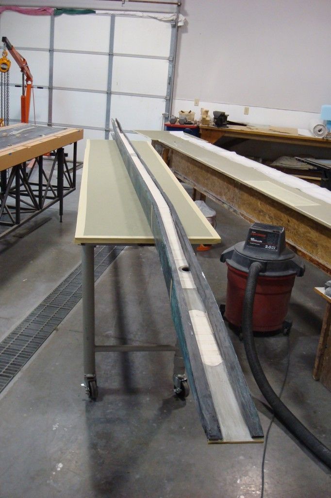
The inner panel shear web connecting the spar flanges is first fit with balsa and later covered with glass. The balsa grain is vertical to the flanges and has varying density depending on the level of stress in particular areas.
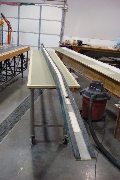
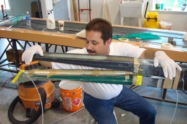
When this photo was taken, the left inner panel spar had been fitted to the wing and the glass shear web is ready to be applied. The glass will be vacuum bagged to the balsa and flanges followed by windings being applied between the spar main wing pins.
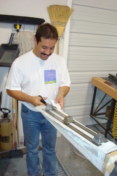
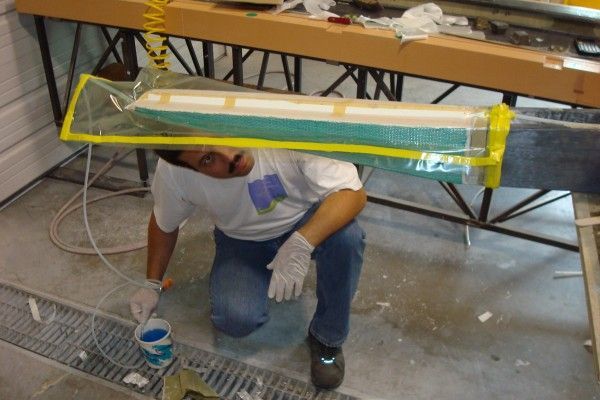
In the photo above, Christian is applying the many layers of dry glass to the stub end of the left wing main spar, which will make the spar windings. The dry glass will be positioned on the spar and then a vacuum bag will be installed to ensure there are no wrinkles in the glass layers. If the glass is wrinkle free then the resin infusion process will commence.
In this photo, Christian is inspecting the stub spar for proper flow of resin from the resin pot to a vacuum manifold and through the fabric making up the windings. The vacuum source is connected to a manifold on the top surface of the shear web.
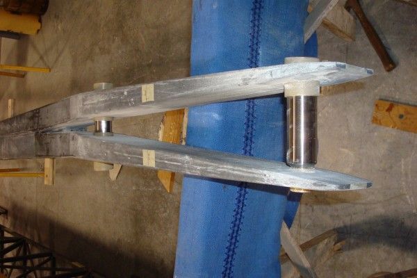
This photo shows the fork end of the main spar with resin infusion on the lower fork. The dark area on the inside of the fork shows resin flowing through the fabric to a vacuum manifold. The top fork area is complete with windings impregnated from a previous day’s resin infusion. In all cases the resin infusion met our design expectations.
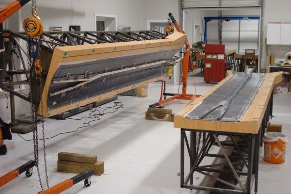
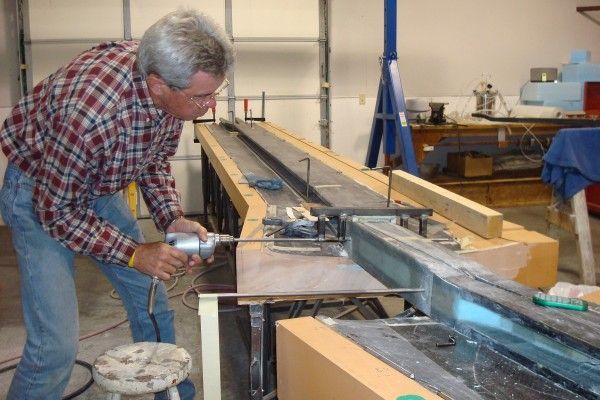
The inner panel spars are shown installed in the bottom wing panels. As discussed previously, the inner panel molds have the capability of alignment without the fuselage such that procedures like this can be performed. Pilot holes are being drilled from which the main wing pin holes will be machined.
After the main wing pin holes were machined, the bushing was bonded in place and trimmed. The wing spar windings and wing pin installation at each of the wing intersection points at 4.8 and 11.5 meters span used a process similar to that shown for the spar location at station 0.0 meters span.
This technology is very impressive. Obviously the Concordia will not go into any sort of mass production.
Hi Dick,
I'm a real fan of your reports from your project, but as I saw the pictures of Christian with our shirt from 1997 European Junior Championship I thought back to that (great) days
And I remember that I still have mine as well 🙂
All the best,
Holger
"Joints at 4,8m and 11.5 meters are similar to joint at 0.00"
I don't follow this
how are pins then installed?
is there an access panel?
I'm following every detail like an addict
Cant get enough
FANTASTIC project, and well thought out.
Nice to see Dick drilling the important holes at 0.00